Theory
A brief overview of the engineering theory and conventions used in this program are illustrated below. Theory is adapted from the Hibbeler textbook [2]. A more rigorous overview of the basic theory behind statically determinate structures is presented in the beambending package documentation here [1].
Indeterminate vs Determinate structures
The determinacy of a structure refers to its solvability mathematically with regards to equilibrium equations.
In maths, when dealing with simultaneous equations, to be able to solve for n number of unknowns we will also need n number of equations (assuming all equations are independent).
For a 1D beam in a 2D space we have 3 equilibrium equations:
\(\sum F_x = 0\)
\(\sum F_y = 0\)
\(\sum M = 0\)
To be able to solve this structure using equilibrium we can only have at most 3 unknowns. A structure which can be solved only by using these equations is referred to as statically determinate.
The determinacy of a structure is a metric defined as the number of unknown reaction forces - the number of equilibrium equations available.
For a statically determinate beam this value is 0.
There are also two more possible cases:
The determinacy is < 0 : In this case the beam is statically unstable
The determinacy is > 0 : In this case the beam is statically indeterminate
An unstable structure is one which is mathematically unsolvable. In this case our object is likely not actually going to be static as it is but will need more supports introduced.
An indeterminate structure is one which mathematically by equilibrium has multiple possible solutions. This is ideal in engineering since if one reaction is removed our structure still has a chance of standing up.
We can actually solve for the forces in indeterminate structures, we just have to look beyond the concept of equilibrium and look at geometrical constraints of our structure.
If you would like for a more detailed explanation of statically determinate structures refer to beambending, the python package upon which this is based upon which deals solely with the statically determinate case.
Indeterminate Calculation Theory
Since our moment equations will never help us to resolve axial forces on our 1D beam, let us consider two independent systems of indeterminacy:
Forces in the x direction
Forces in the y and m direction
If we have more than one unknown in the x direction, or more than two unknowns in the y and m directions collectively, then equilibrium will not be enough to solve for the forces on the beam.
Forces in the x-direction
For a single x restraint we can resolve our unknown force by equilibrium. When we introduce a second restraint we can use our knowledge that both of these restraints will be fixed in space, and hence the axial deformation between them will amount to 0.
For additional supports in the x-direction we know that the displacement between these supports will be 0.
For forces in the x-direction we can get our axial displacement from:
\[e = \int_{0}^L \frac{N(x)}{E(x)A(x)}dx\]
Assuming E*A is constant we can simply integrate our normal force diagram between supports and the result will be 0.
Hence for each additional support in the x direction we can have a new equation, and we can solve for all our unknowns in the x-direction.
Forces in the y-direction and m-direction
For supports totaling a maximum total of two unknowns in the y-direction and m-direction we can solve for our forces with equilibrium. When we introduce an additional unknown, we can use the following geometrical information to help establish additional equations:
For additional supports in the y-direction we know that the vertical displacement will be 0.
For additional supports in the m-direction we know that the slope of the beam will be 0.
We can get slope and vertical displacement equations by integrating the moment equation with respect to x.
\[EIv''(x) = M\]\[EIv'(x) = \int M(x)dx + C_1\]\[EIv(x) = \iint M(x)dx + C_1*x + C_2\]
This introduces two new unknowns, \(C_1\) and \(C_2\), which are the constants for integration. Luckily, we still have our two equilibrium equations so we can solve for the integration constants.
In order to establish the internal moment equation \(M(x)\) as a single equation piecewise functions are a helpful mathematical tool and are used frequently in the python package solution.
Spring Supports
Let me now introduce Hooke’s Law, which states that a spring will deform proportionally to a force applied to it based on its stiffness. Mathematically this is expressed as:
\[F = -k * u\]
where k is a constant value that represents the stiffness of the spring.
Okay so in our solution for indeterminate beams we used the geometrical constraint that the displacement of our supports (u) will be 0. No matter what force the displacement will be 0, and so by Hooke’s law we can see that we have idealised that our support has infinite stiffness.
On the other extreme if we said our spring had 0 stiffness i.e.. k = 0, then no matter how much the beam deflects at that support it will not resist any force. I.e.. there is no reaction, and the support does not actually exist, at least, as a support.
These are two extreme cases but what if we want to simulate a realistic value, one which isn’t approaching some extreme case?
Well then we can reconsider our previous geometric constraints:
For additional supports in the y-direction we know that the vertical displacement will be \(F_{y}/k_{y}\)
For additional supports in the x-direction we know that the displacement between these supports will be \(F_{x2}/k_{x2} - F_{x1}/K_{x1}\)
We have not added any more unknowns, we still have the same equations only with a new term within. Hence our indeterminate solution is still perfectly solvable. Unlike before however, our bending rigidity EI will now affect our reaction forces in our y-m solution and our axial stiffness EA will now our affect our results for our x-force solution.
Sign Convention
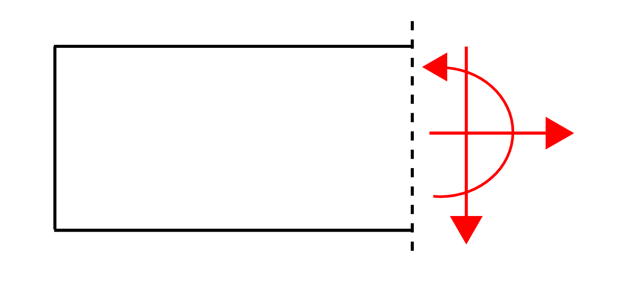
For External Forces the following convention is used:
For x direction: To the right is positive
For y direction: Up is positive
For m direction: Anti-clockwise is positive
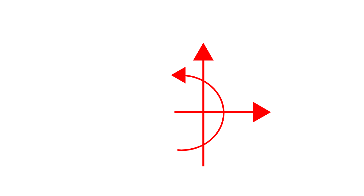
For internal forces considering the left of a cut:
For axial force (x direction): To the right is positive
For shear force (y direction): Down is positive
For moments: Anti-clockwise is positive
For deflections:
Up is considered positive
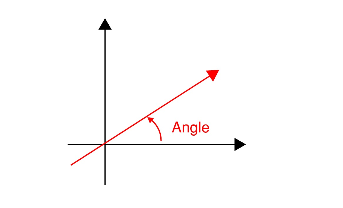
For angled point loads (assuming a positive force is used):
An angle of 0 indicates a positive force to the right
An angle between 0 and 90 indicates a positive force to the right and a positive force up
An angle of 90 indicates a positive force up
An angle between 90 and 180 degrees indicates a force acting left (negative direction) and a positive force acting up
An angle of 180 indicates a negative horizontal force
Unit Convention
The units used throughout the python package are the base SI Units. The following units are adopted in their respective sections of the application.
The default units for length, force and bending moment (torque) are in N and m (m, N, N·m)
The default units for beam properties (E, I, A) are in N and m (N/m2, m4, m2)
The default unit for spring stiffness and distributed loads is N/m
Units can be updated on a beam by using the update_units() method. Adopting this method effects the way input units are considered in calculations and presents graphs dynamically based on the units that have been specified
For example, if units for ‘force’ are changed to ‘kN’ then PointLoad object forces would be interpretted to have a force value in kN. The y-axis for shear force and normal force diagrams would also be in kN and reaction force and point load forces would also be presented in kN. This change would not however effect the presentation of moments which would still appear in N.m.